Cathode Ray Tube (CRT)
Cathode Ray Tube Definition
A cathode ray tube or CRT is a device that produces cathode rays in a vacuum tube and accelerates them through a magnetic and electric field to strike a fluorescent screen to form images.
Cathode Ray Tube History
The eminent physicist Johann Hittorf discovered cathode rays in 1869 in Crookes tubes. Crookes tubes are partially vacuum tubes having two electrodes kept at a high potential difference to discharge cathode rays from the negatively charged electrode cathode. Arthur Schuster and William Crooks proved that cathode rays are deflected by electric and magnetic fields, respectively. In the year 1897, the English physicist J.J. Thomson’s experiments with cathode rays led to the discovery of the electron, the first subatomic particle to be discovered.
The earliest version of the cathode ray tube, Braun Tube, was invented in 1897 by the German physicist Ferdinand Braun. It employed a cold cathode for working. He used a phosphor-coated mica screen and a diaphragm to produce a visible dot. The cathode beam was deflected by a magnetic field only, in contrast to the discharge tube used earlier in the same year by J.J. Thomson, which employed only electrostatic deflection using two internal plates. Braun is also credited with the invention of the cathode ray tube oscilloscope, also known as Braun’s Electrometer.
In 1907, the cathode ray tube was first used in television when Russian scientist Boris Rosing passed a video signal through it to obtain geometric shapes on the screen. Earlier cathode ray tubes used cold cathodes. However, a hot cathode came into existence after being developed by John B. Johnson and Harry Weiner Weinhart of Western Electric. This type of cathode consists of a thin filament heated to a very high temperature by passing an electric current through it. It uses thermionic emissions in vacuum tubes to release electrons from a target.
The first commercial cathode ray tube television manufacture dates back to 1934 by the company Telefunken in Germany. This curved the path for large-scale manufacture and use of CRT TVs until the recent development of Liquid Crystal Displays, Light Emitting diodes, and Plasma TVs.
Cathode Ray Tube Description
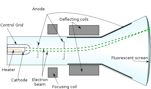
The CRT is composed of three parts.
Electron Gun
This part produces a stream of electrons traveling at very high speeds by the process of thermionic emission. A thin filament is heated up by the passage of alternating current through it. It is used to heat the cathode, generally made of the metal cesium, which releases a stream of electrons when heated to temperatures of about 1750 F. The anode, which is the positively charged electrode, is placed a small distance away and is maintained at a high voltage which forces the cathode rays to gain considerably high accelerations as they move towards it.
The stream of electrons passes through a small aperture in the anode to land in the central part of the tube. There is a grid or a series of grids maintained at a variable potential, which control(s) the intensity of the electron beam reaching the anode. The brightness of the final image formed on the screen is also restricted thus. A monochrome CRT has a single electron gun, whereas a color CRT has three electron guns for the primary colors, red, green, and blue, which overlap among themselves to produce colored images.
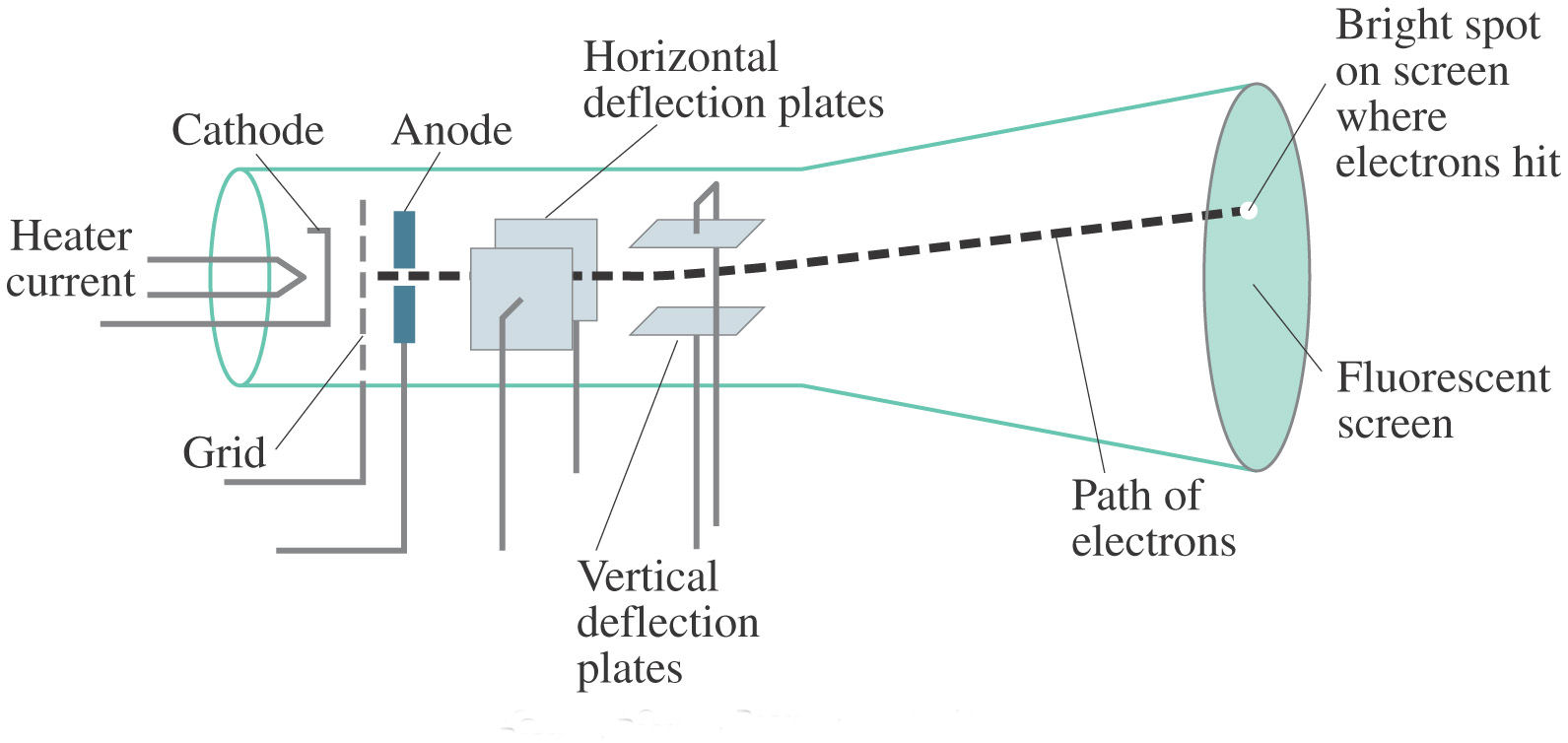
Deflection System
The electron stream, after coming out of the anode, tends to spread out in the form of a cone. But it needs to be focused to form a sharp point on the screen. Also, its position on the screen should be as desired. This is achieved by subjecting the beam to magnetic and electric fields perpendicular to each other. The straight path of the beam then gets deflected, and it hits the screen at the desired point. It should be kept in mind that the anode gives it a considerable acceleration of the order of fractions of the speed of light. This endows the beam with very high amounts of energy.
Fluorescent CRT Screen
This part projects the image for the user’s view. It is given a coating of zinc sulfide or phosphorus which can produce fluorescence. When the highly energetic beam of electrons strikes it, its kinetic energy is converted to light energy, thus forming an illuminated spot on the screen. When complex signals are applied to the deflection system, the bright spot races across the screen horizontally and vertically, forming what is called the raster.
The raster scanning takes place in the same way as we would read a book. That is, from left to right, then go down and back to the left and move right to finish reading the line. This continues until the full screen is finished scanning. However, the CRT scan takes place so rapidly every second that the viewer cannot follow the actual movement of the dot but can see the whole image so produced.
Cathode Ray Tube Mechanism Video
Cathode Ray Tube Experiment by J.J.Thomson
It was already known to the scientific fraternity that cathode rays were capable of depositing a charge, thereby proving them to be the carriers of some kind of charge. But they were not really sure whether this charge could be separated from the particles forming the rays. Hence, the celebrated English physicist J. J. Thomson devised an experiment to test the exact nature.
Thomson’s First CRT Experiment
Thomson took a cathode ray tube, and at the place where the electron beam was supposed to strike, he positioned a pair of metal cylinders having slits on them. The pair, in turn, was connected to an electrometer, a device for catching and measuring electric charges. Then, on operating the CRT, in the absence of any electric or magnetic fields, the beam of electrons traveled straight up to the cylinders, passed through the aptly positioned slits, and made the electrometer register a high amount of charge. So far, the result was quite an expected one.
In the next step, he put a magnet in the vicinity of the cathode ray path that set up a magnetic field. Now, as you may know, an electric field and a magnetic field can never act along the same line. Hence, the charged cathode rays get deflected from their path and give the slits a miss. The electrometer, hence, fails to register anything whatsoever. Thus, he concluded the cathode rays carry the charges along with them wherever they go, and it is impossible to separate the charges from the rays.
Thomson’s Second CRT Experiment
In his second attempt, Thomson tried to deflect the cathode rays by applying an electric field. It could prove the nature of the charge carried by them. There had been attempts before to achieve the end, but they had failed. He thought that if the streams are electrically charged, then they should be deflected by electric fields, but he could not explain why his setup failed to show any such movement.

He later came up with the idea that there was no change from the original path as the stream was covered by a conductor, that is, a layer of ionized air in this case. So he took great pains to make the interior of the tube as close to a vacuum as he could by drawing out all the residual air, and bravo! There was a pronounced deflection in the cathode rays. The great scientist had cleverly put two electrodes, positive and negative, halfway down the tube to produce the electric field. On observing that the beam deflected towards the anode, he could successfully prove that the cathode rays carried one and only one type of charge, negative.
Thomson’s Third CRT Experiment
Thomson tried to calculate the charge-to-mass ratio of the particles constituting the rays and found it to be exceptionally small. That implies the particles have either a very small mass or a very high charge. He decided on the former and gave a bold hypothesis that cathode rays were formed of particles emanating from the atom itself.
Experiment Summary
By using certain modifications in the regular CRT, Thomson’s cathode ray tube experiment proved that cathode rays consist of streams of negatively charged particles having smaller masses than that atoms. It was highly likely for them to be one of the components of atoms.
Cathode Ray Tube Applications
Oscilloscope
It measures the changes in electrical voltage with time. If the horizontal plate is attached to a voltage source and the vertical to a clocking mechanism, then the variations in the magnitude of the voltage will show up on the CRT monitor in the form of a wave. With an increase in voltage, the line forming the wave shoots up while it comes down if the voltage is low. If, instead of a variable voltage source, the horizontal plates are connected to a circuit, then the arrangement can be used to detect any sudden change in its voltage. Thus, it can be used for troubleshooting purposes.
Televisions
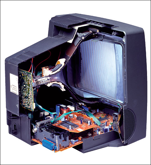
Before the emergence of lightweight LCD and plasma TVs, all televisions were bulky and had cathode ray tubes in them. They had a very fast raster scan rate of about 1/50th of a second. In a color TV, the persistence of the different colors would last for only the time between two consecutive scans. If it stayed longer, then the tube would produce blurred images. But if the effect of the colors ended before the next scan, then it gave rise to a flickering screen. Modern tube TVs use flat-screen CRTs, unlike their yesteryear counterparts.
Cathode Ray Tube Amusement Device

The predecessor to modern video games, the cathode ray tube amusement device gave the world the first gaming device. The CRT produced electronic signals in the form of a ray of light. Controller knobs in the tube were then used to adjust the trajectories of light so that it could hit on a target imprinted on a clear overlay attached to the CRT display screen. The game was conceptualized on World War II missile displays and created the effect of firing missiles at targets.
Other Applications
Cathode ray tube monitors are widely used as display devices in radars. However, the CRT computer monitor has gradually become obsolete with the introduction of TFT-LCD thin panel monitors.
Health Risks
Ionizing Radiation: CRTs can emit a small amount of ionizing radiation that needs to be kept under control by the Food and Drug Administration Regulations in 21 C.F.R. 1020.10. However, most CRTs manufactured after 2007 have much lesser emissions than the prescribed limit.
Flicker: Low refresh rates, 60Hz and below, can produce flicker in most people, although the susceptibility of eyesight to flicker varies from person to person.
Toxicity: Modern-day CRTs may have their rear glass tubes made of leaded glass, which is difficult to dispose of as they can cause an environmental hazard. Some of the older versions also contain cadmium and phosphorus, making the tubes highly toxic. Special cathode ray tube recycling processes fulfilling the norms of the United States Environmental Protection Agency should be followed.
Implosion: Very high levels of vacuum inside a CRT can cause it to implode if there is any damage to the covering glass. This is caused by the high atmospheric pressure, which forces the glass to crack and fly off at high speeds in all directions. Though modern CRTs have strong envelopes to prevent shattering, they should be handled very carefully.
Noise: The signal frequencies used to operate CRTs are of a very high range and are usually imperceptible to the human ear. However, small children can sometimes hear very high-pitched noises near CRT televisions. That is because they have a greater sensitivity to hearing.
The cathode ray tube was a useful invention in Science for the discovery of an important fundamental particle like an electron and also opened up newer arenas of research in atomic Physics. Until about the year 2000, it was the mainstay of televisions all over the world before being forced into oblivion due to the emergence of newer technologies.
-
References
Article was last reviewed on Tuesday, May 9, 2023
Related articles

One response to “Cathode Ray Tube (CRT)”
Leave a Reply


Join our Newsletter
Fill your E-mail Address
I want to ask that in cathode ray tube tv why electrons are never finish which is on cathode while the material have limited electrons