Brayton Cycle
The Brayton cycle is a thermodynamic cycle that describes the workings of a constant-pressure gas engine, such as modern gas turbine engines and airbreathing jet engines. It extracts energy from compressed air and fuel to generate valuable work. The work produced by the Brayton cycle drives many vehicles by giving them thrust.
Brayton cycle is named after American engineer George Brayton, who developed and patented a constant pressure engine in 1872. It formed the basis of the gas turbine engine.
Theory
A gas turbine engine consists of three main components: compressor, combustor, and turbine. Air is compressed in the turbine compressor. It is mixed with fuel and combusted under constant pressure in the combustor. The resulting hot gas is made to expand through the turbine to perform work. Most of the work produced in the turbine is utilized to run the compressor. The rest is available to run secondary equipment and generate power. The turbine provides adequate power to drive the compressor and generate mechanical power.
PV and TS Diagrams
Although the Brayton cycle usually runs as an open cycle system, it is convenient for thermodynamic analysis to assume that the exhaust gases are reutilized in the intake. Therefore, the analysis can be done for a closed system called the ideal Brayton cycle. The ideal Brayton cycle consists of four processes described below with the corresponding PV and TS diagrams.
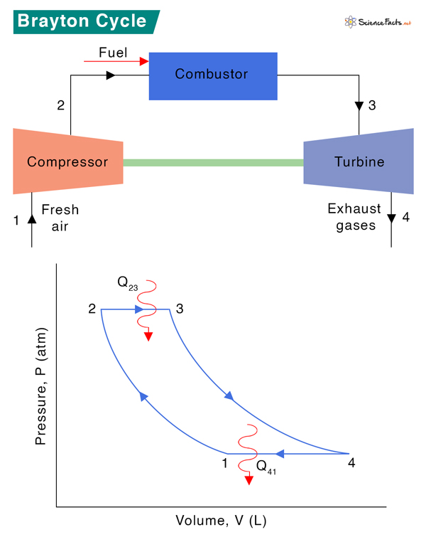
Process 1 → 2: Isentropic Compression
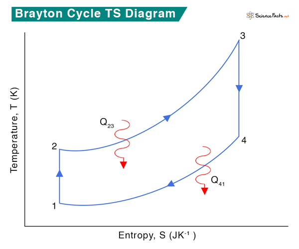
Fresh ambient air is drawn into the compressor and compressed from pressure P1 to P2. The volume reduces from V1 and V2, and the temperature increases from T1 to T2. The entropy, S, remains constant: S1 = S2.
Process 2 → 3: Heat Addition
Fuel and compressed air are sent to the combustor, where fuel burns at constant pressure, P2 = P3. Heat is added to the compressor. The temperature rises from T2 to T3, volume expands from V2 to V3, and entropy increases from S2 to S3.
Process 3 → 4 Isentropic Expansion
The heated and compressed gas expands adiabatically through a turbine. The gas works on the turbine’s blades and loses its internal energy, which is equivalent to work that leaves the system. The pressure decreases from P3 to P4, temperature decreases from T3 to T4, and volume slightly increases from V3 to V4. The process is isentropic, which means S3 = S4.
Process 4 → 1 Heat Rejection
Isobaric heat rejection occurs in this process at constant pressure, P4 = P1. A slight decrease in volume from V4 to V1 occurs due to heat rejection. Since it is a heat rejection process, the gas temperature decreases from T4 to T1, and entropy reduces from S4 to S1.
Thermal Efficiency
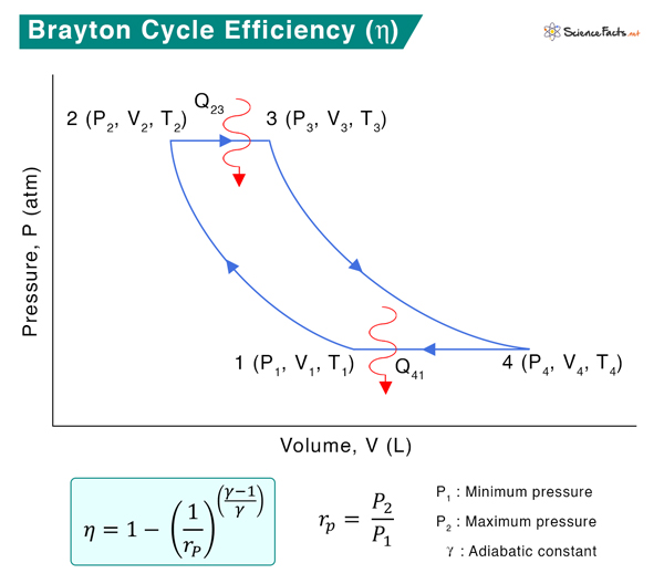
The general expression for thermal efficiency is given by
Heat is added to during the constant-pressure process 2 → 3 and is given by
Q23 = CP (T3 – T2)
Heat is rejected during the constant-pressure process 4 → 1 and is given by
Q41 = CP (T1 – T4)
Where Cp is the specific heat at constant pressure.
According to the first law of thermodynamics, the net change in internal energy is zero for a closed circle.
Δu = 0
=> (Q12 – W12) + (Q23 – W23) + (Q34 – W34) + (Q41 – W41) = 0
Q12 = Q34 = 0 (since they are adiabatic processes)
Therefore,
Q23 + Q41 – (W12 + W23 + W34 + W41) = 0
=> Q23 + Q41 – W = 0
=> W = Q23 + Q41
Where W = W12 + W23 + W34 + W41 is the net work done.
Therefore,
Adiabatic gas equations give
Where γ is the adiabatic constant. Since P2 = P3 and P4 = P1
The efficiency equation is reduced to
Here, T1 is the initial temperature of the undisturbed gas, T2 is the initial temperature before the combustion, T3 is the final temperature of the combustion process, and T4 is the temperature of the gas after it leaves the turbine. The smaller the T1/T2 ratio, the higher the efficiency. Therefore, if more heat is added and less heat is lost during the engine operation, the thermal efficiency of the Brayton cycle will be high.
Rewriting the above equation as
Therefore,
The pressure ratio in most modern engines ranges from 11 to 16.
-
References
Article was last reviewed on Tuesday, December 12, 2023
Related articles


Join our Newsletter
Fill your E-mail Address