Electromagnetic Induction
What is Electromagnetic Induction
When a conductor, such as a loop of wire or a coil, moves through a magnetic field, the magnetic flux passing through it changes with time. Since the cross-sectional area of the loop is fixed, the change in flux is caused by the changing magnetic field. This changing magnetic field applies force to the free electrons in the conductor. As a result, these electrons move and produce a current inside the conductor. This current is known as induced current.The potential difference between any two points in the conductor is known as induced emf (electromotive force). The process of generating an electric current by a changing magnetic field is called electromagnetic induction.
The magnetic field comes from a permanent magnet like a bar magnet. The phenomenon is called induction because there is no physical contact between the conductor and the magnet. The magnetic lines of force pass through air or medium if the coil is wrapped around a metallic core. A condition of electromagnetic induction is that there should be a relative motion between the conductor and the magnet.
Who Discovered Electromagnetic Induction
English physicist Michael Faraday discovered electromagnetic induction in 1831. Scottish physicist and mathematician James Clerk Maxwell developed the mathematical equations and published them in 1865. These equations are today known as Maxwell’s equations.
How does Electromagnetic Induction Work
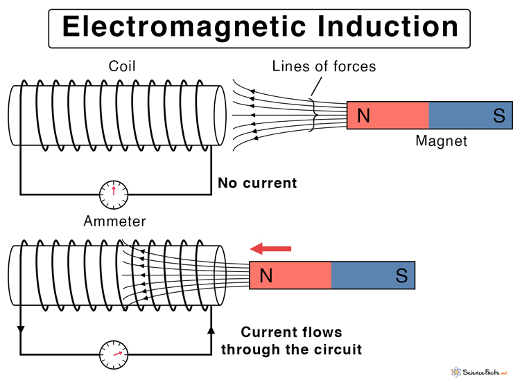
Electromagnetic induction is best explained when a conducting wire wound into a coil is placed near a moving bar magnet having a north and a south pole. The magnetic field in the bar magnet is represented by lines of forces that come out from the north pole and terminate into the south pole. The number of lines passing through a given area in space is the magnetic flux.
Magnetic Flux Equation
Suppose the bar magnet a field of strength B. Consider a two-dimensional area A in space such that the lines of force pass through this area and make an angle θ with the area vector. Then, the area projected on a plane perpendicular to the field is A cos θ. The magnetic flux φ is defined as the product of the field and the projected area.
φ = BA cos θ
When the north pole is brought closer to the coil, the flux increases and will continue to increase as long as the magnet is in motion. The change in magnetic flux over time results in an induced current. If an ammeter is connected to the two ends of the coil, it will register a current. The current will continue to flow as long as the magnet is moving. If the magnet is retracted from the coil, the induced current will change direction.
Laws of Electromagnetic Induction
1. Faraday’s Law
As current is induced in the circuit, there will also be an induced voltage or emf (electromotive force) due to the wire’s resistance. According to Faraday’s law, the magnitude of this emf is proportional to the rate of change of the flux. This law establishes a quantitative relationship between the changing magnetic field and the induced emf in an electromagnetic circuit.
Faraday’s Law Equation
Suppose the coil has N turns. It is placed in a magnetic field such that dφ/dt represents the flux rate. The formulas for induced emf ε are given by,
ε = – N dφ/dt (continuous)
ε = – N Δφ/Δt (discrete)
SI Unit of EMF: Volts
The negative sign is because the induced emf opposes the very reason causing it, which is dictated by Lenz’s law.
Factors that Effect Electromagnetic Induction
1. Number of Turns: The induced voltage is directly proportional to the number of turns of the wire. Therefore, the higher the number of turns, the higher is the voltage produced.
2. Changing Magnetic Field: The induced voltage is directly proportional to the flux rate. Changing the magnetic flux affects the induced voltage. This change can be done by moving the magnet closer to or away from the coil and vice-versa.
2. Lenz’s Law
Faraday’s law does not state anything about the conservation of energy. Lenz’s law can explain the negative sign in Faraday’s law equation. Lenz’s law states that “The polarity of the induced emf is such that it opposes the change in magnetic flux that produced it.” In other words, an induced current will always oppose the motion that started it in the first place. Therefore, Lenz’s law can determine the direction of induced current.
Lenz’s law is named after German physicist Heinrich Friedrich Lenz after he deduced it in 1834.
Examples and Applications of Electromagnetic Induction
Here are some examples, uses, and applications of electromagnetic in real and daily life.
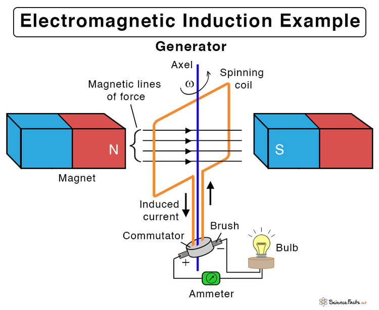
- Electric generator: It converts kinetic energy into electrical energy and produces electricity in power plants. The electricity is then supplied to homes.
- Electric transformer: It changes the voltage and comes in two types – step up and step down. A step-up transformer increases the voltage, while a step-down transformer decreases the voltage.
- Dynamo: It is a small generator consisting of a permanent magnet that is rotated inside a fixed coil by the movement of a bicycle wheel.
- Inductance: It is a simple coil with a ferromagnetic core and is usually a part of an electrical circuit. It stores energy in the magnetic field of the coil when current passes through it.
Advantages of Electromagnetic Induction
Here are some benefits of electromagnetism.
- Cheap, simple, reliable, efficient, and controllable
- Mechanical energy can be converted directly into electrical energy
- Produces electric current and powers homes
Example Problems and Solutions
P.1. A closed coil of 50 turns and area 150 cm2 is rotated in a magnetic field of flux density 2 Wb m-2. It rotates from a position where its plane makes an angle of 45˚ with the field to a position perpendicular to the field in a time of 0.3 sec. Find the magnitude of the emf induced in the coil due to its rotation.
Soln. Given,
N = 50
B = 2 Wb m-2
A = 150 cm2 = 150 x 10-4m2 = 0.015 m2
θ = 45˚
Δt = 0.3 s
Initial flux: φi = BA cos θi = 2 Wb m-2 x 0.015 m2 x cos 45˚ = 0.021 Wb
Final flux: φf = BA cos θf = = 2 Wb m-2 x 0.015 m2 x cos 0˚ = 0.03 Wb
Therefore, Δφ = φf – φi = 0.03 – 0.021 = 0.009 Wb
Therefore, the magnitude of induced emf is,
|ε| = N Δφ/Δt = 50 x 0.009 Wb/0.3 s = 1.46 V
P.2. A uniform magnetic field is normal to the plane of a circular loop 15 cm in diameter and made of copper wire of diameter 3 mm. (a) Calculate the resistance of the wire (R = ρl/A, the resistivity of copper: ρ = 1.68 x 10 -8 Ωm). (b) At what rate must the magnetic field change with time if an induced current of 15 A forms in the loop?
Ans. (a) Given,
d = 3 mm = 3 x 10⁻³ m
ρ = 1.68 x 10 -8 Ωm
D = 15 cm = 0.15 m
Length of the wire = πD
Cross-sectional area of the wire = πd2/4
Therefore,
R = ρl/A = ρπD/(πd2/4) = 4ρD/d2 = 4 x 1.68 x 10 -8 Ωm x 0.15 m / (3 x 10⁻³ m)2 = 0.00112 Ω = 1.1 x 10⁻³ Ω
(b) Given,
I = 15 A
R = 1.1 x 10⁻³ Ω
N = 1
Therefore,
V = IR = 15 A x 1.1 x 10-3 Ω = 0.0168 V
From Faraday’s law,
|ε| = Δφ/Δt
Or, Δφ/Δt = 0.0168 V
Or, Δ(BA)/Δt = 0.0168 V
Or, ΔB/Δt = 0.0168 V/A =0.0168 V/(πD2/4) = 0.0168 V/(π(0.15m)2/4) = 0.95 V/m2 = 0.95 (V.s/m2).(1/s) = 0.95 T/s
-
References
Article was last reviewed on Wednesday, February 1, 2023
Related articles


3 thoughts on “Electromagnetic Induction”
Leave a comment

Join our Newsletter
Fill your E-mail Address
I want more information About this topic
Pls leave more information about Electromagnetic Induction.
Pretty sure the direction of the current in the first illustration is wrong (at the time of commenting), as it violates Lenz’s law: if the magnet is being pushed north pole first towards the coil, the induced current would flow in the opposite direction.
Please either correct the direction of the current or the direction of the magnet’s movement.
The induced current is in fact opposite to the very reason it is due. Please check carefully.