Half Wave Rectifier
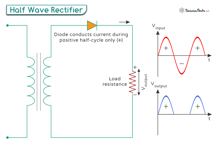
A half wave rectifier is an electronic circuit that converts alternating current (AC) into direct current (DC). An AC signal comprises a wave that rises above and falls below a central line (sinusoidal wave). A half wave rectifier employs a single diode that allows current flow only during one half-cycle of the input AC signal and blocks it during the other half.
A half wave rectifier differs from a full wave rectifier in that the latter rectifies the AC signal during both halves of the AC input signal.
Working Principle
Circuit Components: The operation of a half wave rectifier revolves around its straightforward circuit configuration and the behavior of its primary component, the diode. The circuit comprises an input AC source connected in series with a load resistor and a diode, forming a basic setup for rectification.
Positive Half-Cycle: During the positive half-cycle of the input AC voltage, the diode becomes forward-biased, allowing current to flow through the load resistor. This current passes through the load resistor, producing a voltage across it.
Negative Half-Cycle: During the negative half-cycle, the diode becomes reverse-biased, blocking the current flow. Consequently, no current flows through the load resistor, and no voltage is produced across it.
Output Waveform: This action causes the output across the load resistor to resemble a series of pulses that represent only the positive half-cycles of the input AC signal. This is why it is called a half wave rectifier—only half of the input waveform (the positive half) is used.
Pulsating DC: These pulses are not smooth DC but rather a pulsating DC signal. The DC voltage across the load resistor is the same as the peak voltage of the input AC signal minus the forward voltage drop across the diode.
Half Wave Rectifier Circuit with Capacitor
We have seen how a half wave rectifier converts an AC signal into DC. However, the output is not smooth and exhibits a pulsating nature, meaning it has many ripples and fluctuations.
To make the DC output smooth and stable, we use filters. Filters are crucial electronic components that reduce ripples by converting the pulsating DC waveforms into stable, constant signals. This process is known as ‘smoothing’. Smoothing out these fluctuations becomes imperative to render the pulsating waveform usable in real-world applications.
In practical applications, using half wave rectifiers in conjunction with a filter is essential. Among potential filtering components like capacitors or inductors, the capacitor filter remains the prevalent choice due to its widespread usage and effectiveness in smoothing out the output waveform.
Performance Metrics
The following performance metrics play a crucial role in evaluating the effectiveness of a half wave rectifier in converting AC to DC:
1. Ripple Factor (γ)
The ripple factor measures the amount of AC component in the rectified output. It is a vital parameter for assessing the smoothness of the output DC waveform. It is calculated as the ratio of the root mean square (RMS) value of the AC component to the average (DC) value of the rectifier output. The formula for ripple factor (γ) is given by
For voltage:
For current:
Where:
- Vrms is the RMS value of the AC voltage.
- VDC is the average value of the output voltage.
- Irms is the RMS value of the AC current.
- IDC is the average value of the output current.
A higher ripple factor implies a more significant amount of ripple in the output, indicating a less stable DC voltage level. For a half wave rectifier, the ripple factor is about 1.21.
2. Rectification Efficiency (η)
Efficiency refers to the ability of the rectifier to convert the input AC power into usable DC power. Efficiency (η) for a half wave rectifier is the ratio of DC output power to the AC input power multiplied by 100%. The formula for efficiency is
Where:
- PDC represents the DC output power.
- PAC denotes the AC input power.
A higher efficiency indicates that a larger percentage of the input power is converted into useful DC power. In comparison, a lower efficiency signifies more power loss, typically due to diode losses and the absence of the negative half-cycle utilization in this rectifier configuration. Half wave rectifiers have an efficiency of about 40.6 %.
3. Peak Inverse Voltage (PIV)
It is the maximum voltage the diode can withstand in reverse-biased condition without breaking down. For a half wave rectifier, the PIV is equal to the peak value of the input AC voltage.
PIV = Vpeak
Where Vpeak is the maximum value of the AC input voltage.
4. Form Factor (FF)
The form factor quantifies the shape or form of the waveform relative to its RMS value. It is the ratio of the RMS value of the output current to its average value. The following formula gives its value:
5. Peak Factor (PF)
The peak factor is the ratio of the peak value of the output voltage to the RMS value.
-
References
Article was last reviewed on Tuesday, June 18, 2024
Related articles


Join our Newsletter
Fill your E-mail Address