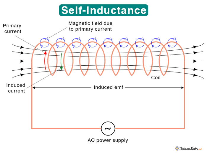
Self-Inductance
Self-inductance is a property of a coil and results from electromagnetic induction. From Faraday’s law, a current-carrying wire produces a magnetic field. When the current changes, the magnetic field also changes. An emf (electromotive force) is induced in the same coil. The direction of the emf is such that it opposes the change in current. In other words, the direction of the induced current is opposite of the primary current.
American scientist Joseph Henry discovered inductance in 1831.
Self-Inductance Equation
Faraday’s law can be used to derive the self-inductance of a coil. According to Faraday’s law of electromagnetic induction, the induced emf ε in a coil with N turns is given by
The above equation states that the induced emf is proportional to the number of turns and the rate of change of flux. It means that if the number of turns increases or the frequency of flux increases, the induced emf also increases.
It is easier to measure the current than flux in a closed circuit. According to Ampere’s law, the magnetic field is directly proportional to the current. Hence, the magnetic flux is also proportional to the current.
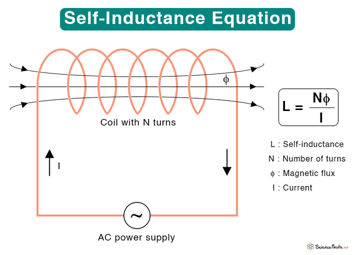
The constant of proportionality L is the self-inductance of the coil. Since the coil has N turns, the above equation can be rewritten as follows.
Where
L : Self-inductance
N : Number of turns of the coil
φ : Magnetic flux
I : Current
Going back to Faraday’s law.
Symbol: L
SI Unit: Henry or H (1 H = 1 Wb/A = 1 T·m2/A)
The equation L = Nφ/I can determine the self-inductances of solenoid and toroid.
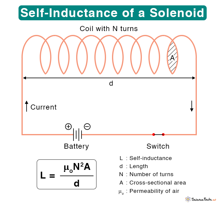
1. Self-Inductance of a Solenoid
Consider a solenoid of length d and cross-sectional area A, as shown in the figure. Suppose the solenoid has N turns. When a current I flows in the solenoid, the magnetic field B inside is given by
The magnetic flux φ through a single turn of cross-sectional area A is
The self-inductance of the solenoid is given by
Where
L : Self-inductance
N : Number of turns of the solenoid
A : Cross-sectional area of the solenoid or area of each turn
d : Length of the solenoid
μo : Permeability of air
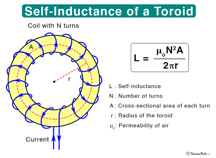
2. Self-Inductance of a Toroid
Consider a toroid of radius r and N turns, as shown in the figure. Suppose a current I passes through the coil. Then, the magnetic field B is given by
The magnetic flux φ through a single turn is
Therefore, the self-inductance is given by
Where
L : Self-inductance
N : Number of turns of the coil
A : Cross-sectional area of each turn
r : Radius of the toroid
μo : Permeability of air
From the above two equations for solenoid and toroid, one can see that the self-inductance depends on the device’s geometry and the number of turns of the coil. A coil with many turns will have a higher inductance than a coil with few ones. Also, by increasing the area of the coil or decreasing its length, the inductance can be increased.
The inductance can be increased further if the coil is wound on a ferromagnetic core instead of a non-ferromagnetic core or hollow core. The reason is that ferromagnetic materials like iron, cobalt, or nickel concentrate the magnetic lines of force intensely through the core. In this case, the permeability of air μo is replaced by the permeability of the core material μ.
Uses and Applications
- Allows traffic signals to sense vehicles waiting at the street intersection
- Allows metals detectors to detect metal when a person passes through it
- Allows a choke in a radio frequency circuit to oppose any change in current and let direct current flow through
Problems and Solutions
Problem 1: Calculate the self-inductance of a 15 cm long, 5 cm diameter solenoid with 250 coils (μo = 1.26 x 10⁻⁶ H/m).
Solution:
Given,
L = 15 cm
D = 5 cm
N = 250
The area is given by
A = πD2/4 = π (5 x 10⁻²)2 m2/4 = 1.96 x 10⁻³ m2
Therefore, the self-inductance of the coil is
L = μoN2A/d = (1.26 x 10⁻⁶ Hm-1 x 2502 x 1.96 x 10-3 m2)/(15 x 10-2 m)
Or, L = 0.001 H or 1 mH
Problem 2: An induced emf of 2.5 V is measured across a coil of 150 closely wound turns while the current through it increases uniformly from 0 to 6 A in 0.20 s. (a) What is the self-inductance of the coil? (b) With the current at 6 A, what is the flux through each turn?
Solution:
Given,
ε = 2.5 V
ΔI/Δt = (6 A – 0 A) /0.2 s = 30 As-1
N = 150
I = 6 A
a) Therefore, the self-inductance is
L = |ε/(ΔI/Δt)|
Or, L = 2.5 V/30 As-1 = 0.083 H or 83 mH
b) The flux is given by
φ = LI/N
Or, φ = 0.083 H x 6 A/150 = 0.003 Wb
-
References
Article was last reviewed on Thursday, February 2, 2023
Related articles


Join our Newsletter
Fill your E-mail Address