Full Wave Rectifier
A full wave rectifier is an electronic circuit that converts alternating current (AC) to direct current (DC). An AC current flows in both directions, while a DC current flows in one direction only. An AC signal comprises a wave that rises above and falls below a central line, called a sinusoidal wave. A full wave rectifier rectifies the AC signal during both halves. It flips the negative half into a positive one, resulting in a continuous current flow in a single direction.
A full wave rectifier differs from a half wave rectifier in that the latter rectifies the AC signal only during the positive half and shuts down during the negative half.
Operation of a Full Wave Rectifier
Components
- Diodes: They allow current to flow in one direction while blocking it in the opposite direction.
- Transformer: It is used to step up or step down the AC voltage to the desired level.
- Load Resistance: It represents the device where the rectified and smoothed DC voltage is applied and measured.
Types
There are two main types of full wave rectifiers, which differ in their circuits.
1. Center-Tapped Rectifier
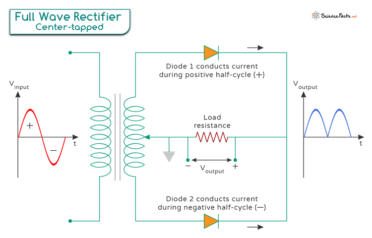
A center-tapped rectifier is the most common type of full wave rectifier and best describes its general operations. It consists of a transformer with a center-tapped secondary winding and two diodes. The center-tapped transformer divides the secondary winding into two halves, allowing for a more efficient conversion of AC to DC. The image above explains the operation of a center-tapped rectifier.
During the positive half-cycle of the input AC voltage, one of the diodes (D1) becomes forward-biased and conducts, allowing current to flow through the load connected to the output terminals. Simultaneously, the other half of the secondary winding remains in the reverse bias state. During the negative half-cycle, the polarity reverses, causing the other diode (D2) to conduct, thus ensuring a continuous current flow through the load resistance in the same direction.
This configuration allows both halves of the input AC cycle to be utilized, resulting in a higher efficiency than a half wave rectifier.
2. Bridge Rectifier
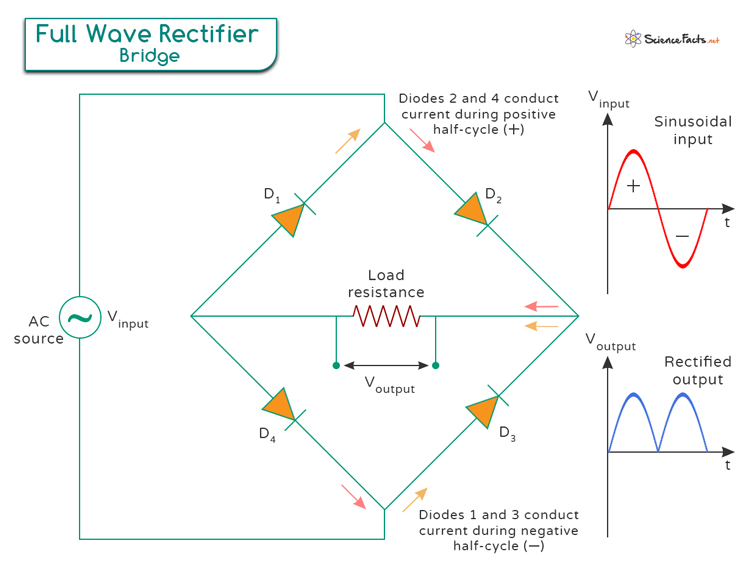
The full wave bridge rectifier uses four diodes arranged in a bridge configuration, with the input AC voltage applied across two opposite corners and the output DC voltage obtained across the load resistance. During each half-cycle of the AC input, two diodes are forward-biased, allowing current to flow through them toward the output terminal, while the other two diodes are reverse-biased. This results in a unidirectional current flow and a higher average output voltage than a half wave rectifier.
Output Characteristics of a Full Wave Rectifier
The output of a full wave rectifier is characterized by a pulsating direct current (DC) signal, which results from the rectification of both the positive and negative halves of the alternating current (AC) input. Unlike a half wave rectifier that only uses one-half of the AC waveform, a full wave rectifier flips the negative half to positive, producing a waveform that pulsates with twice the frequency of the input AC. This means if the input AC is at 60 Hz, the output will have a ripple frequency of 120 Hz. Although the output is not a smooth DC signal but a series of peaks, it has a higher average voltage and is easier to filter into a steady DC output using capacitors and other smoothing components.

Performance Metrics
The performance of a full wave rectifier can be evaluated based on several key metrics, including:
1. Ripple Factor (γ)
This metric quantifies the amount of AC component or ripple in the rectified output. It is calculated using the formula:
Where:
- Vrms is the RMS (root mean square) value of the AC component of the output voltage.
- VDC is the DC component of the output voltage.
The ripple factor for a full wave rectifier is approximately 0.48, assuming an ideal condition (no load resistance or filtering).
2. Rectification Efficiency (η)
It measures the efficiency of the rectifier in converting AC input power into DC output power. The rectification efficiency (η) can be calculated as:
Where:
- PDC is the DC output power.
- PAC is the AC input power.
The rectification efficiency of a full wave rectifier, under ideal conditions, is around 81.2%.
3. Peak Inverse Voltage (PIV)
It refers to the maximum voltage across the diodes in the reverse-biased direction during the negative half-cycle of the input AC.
For a full wave bridge rectifier, the PIV across each diode is equal to the peak value of the input AC voltage.
For a center-tapped rectifier, the PIV across each diode is equal to twice the peak value of the input AC voltage.
Where Vpeak is the maximum value of the AC input voltage.
4. Form Factor (FF)
The form factor is a measure that indicates the shape or form of the output waveform relative to its average or RMS (root mean square) value. For a full wave rectifier, the form factor is given by the ratio of the RMS value to the average value of the output voltage. It is expressed as:
Where:
- Vrms is the RMS value of the output voltage.
- Vavg is the average value of the output voltage.
For a full wave rectifier, the output voltage is a pulsating DC with ripple, and the form factor is approximately 1.11, assuming ideal conditions and no load resistance or filtering.
5. Peak Factor (PF)
Peak factor is a measure that indicates the ratio of the peak value of the output voltage to its RMS value. It quantifies the extent of variation or peaks in the waveform compared to its average value. The peak factor for a full wave rectifier is calculated as:
Where:
- Vpeak is the peak value of the output voltage.
- Vrms is the RMS value of the output voltage.
The peak factor for a full wave rectifier is approximately 1.414, considering ideal conditions.
Applications of Full Wave Rectifier
Full wave rectifiers are fundamental components in many electronic devices, providing a steady DC voltage for their operation. Its applications include:
- Power supply circuits to convert AC to DC.
- Signal demodulation in communication systems.
- DC motor drives.
- Battery charging circuits.
Advantages and Disadvantages of Full Wave Rectifier
Advantages
- Higher Efficiency: Utilizes both halves of the AC waveform, resulting in a higher average output voltage than a half wave rectifier.
- Higher Output Voltage: Provides a greater average DC output voltage, making it more effective for powering electronic devices.
- Reduced Ripple: Produces a higher ripple frequency (twice the input AC frequency), which is easier to filter and smooth into a steady DC signal.
- Better Transformer Utilization: In the case of center-tap rectifiers, the transformer utilization is more efficient as the entire secondary winding is used.
Disadvantage
The only disadvantage is that it requires more components (four diodes for a bridge rectifier and two diodes for a center-tapped transformer), making the circuit more complex and potentially more expensive.
-
References
Article was last reviewed on Tuesday, July 23, 2024
Related articles


Join our Newsletter
Fill your E-mail Address