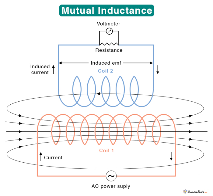
Mutual Inductance
According to Faraday’s law, a current-carrying wire produces a magnetic field. If the current changes with time, the magnetic field will also change. Suppose the wire is wound into a coil and another coil is brought closer to it. Then, the changing magnetic field in the first coil will induce an emf (electromotive force) in the second. This phenomenon is known as mutual induction. The property that links the two coils by a common magnetic field is known as mutual inductance.
The induced emf will cause a current to flow in the second coil. Lenz’s law determines the direction of the induced current. This direction is such that it will oppose the change of current in the first coil. Now, suppose both the coils carry current. Then, emf will be induced in each coil due to changing current in the other. Hence, mutual inductance can also be defined as the property that describes the effect on one coil’s magnetic field with another coil’s magnetic field.
Mutual Inductance Equation
Suppose two coils are placed next to each other. The first coil has N1 turns and carries current I1 giving rise to magnetic field B1. The second coil has N2 turns. Since the two coils are close, some of the magnetic field lines through coil 1 will also pass through coil 2. Let φ21 denote the magnetic flux through one turn of coil 2 due to I1. According to Faraday’s law, changing the current I1 changes the magnetic flux φ21. It results in an induced emf ε21 given by the following formula.
The rate of magnetic flux change in coil 2 is proportional to the rate of current change in coil 1. Therefore,
The constant of proportionality M21 is the mutual inductance. It has the SI unit of Henry or H, named after American scientist Joseph Henry who discovered electromagnetic induction. 1 H = 1 Wb/A or 1 T·m2/A or 1 V·s/A.
Rewriting the induced emf equation
Thus, the mutual inductance can be defined as the ratio between the emf generated in coil 2 and the rate of current change in coil 1. It is also known as the coefficient of mutual induction.
Now, consider the following equation again.
The above equation is discrete in time. So, summing over all time increments we get
This equation is used to calculate the mutual inductance between any two coils, as discussed below.
1. Mutual Inductance of Two Coils
Suppose two coils 1 & 2 with N1 and N2 turn have currents I1 and I2 flowing through them, as shown in the figure. The flux due to I1 and I2 are φ21 and φ12. The mutual inductance of coil 2 due to coil 1 is given by
Similarly, the mutual inductance of coil 1 due to coil 2 is given by
From the reciprocity theorem, the two mutual inductances are the same and can be represented by M. Therefore,
The induced emfs in the two coils are given by
Note that ε21 and ε12 do not represent the total emf in the circuit. Each coil can have its emf due to self-inductance.
The mutual inductance depends upon how close the two coils are placed. If the coils are close enough, all the flux from coil 1 passes through coil 2. Then the mutual inductance is high. The mutual inductance is low if the coils are far. Also, the mutual inductance can be increased by increasing the number of turns of the coils or by enclosing the coils in a soft iron core. The advantage of having a soft iron core is that the magnetic flux leakage is reduced.

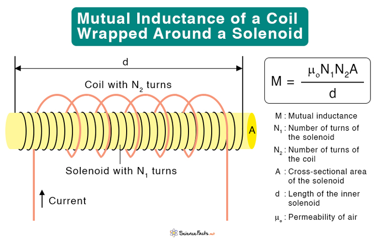
2. Mutual Inductance of a Coil Wrapped Around a Solenoid
Suppose a long solenoid with length d and cross-sectional area A consists of N1 turns of wire carries current I1, as shown in the figure. The magnetic field B inside a solenoid is given by
Where μo (= 1.26 x 10⁻⁶ H/m) is called the permeability of air.
A coil of N2 turns is wrapped around the solenoid such that the two are coaxial. The magnetic flux φ21 passing through each turn of the coil due to the solenoid is
Thus, the mutual inductance is
The self-inductance of a solenoid is
Similarly, the self-inductance of the coil can be calculated and shown to be
Multiplying L1 with L2, we get
However, this equation assumes no flux leakage and perfect magnetic coupling between the two coils, L1 and L2. In reality, there is going to be some leakage due to alignment and the coupling can never be 100%. For this reason, we introduce a term calling coupling constant, k, such that the mutual inductance becomes
k takes a value between 0 and 1. When k = 1, it means that all of the magnetic flux produced by the solenoid passes through the outer coil and vice versa.
Applications of Mutual Inductance
Mutual inductance is widely used in daily life, especially in the following devices.
- Transformers
- Generators
- Motors
- Metal detectors
- Pacemakers
- Radio receivers
Problems and Solutions
Problem 1: Two coils have a mutual inductance of 4.75 × 10⁻⁴ H. The current in the first coil increases at a uniform rate of 940 A/s. What is the magnitude of induced emf in the second coil?
Solution:
Given
M = 4.75 × 10⁻⁴ H
ΔI/Δt = 940 A/s
The induced emf is given by
|ε| = M ΔI/Δt = 4.75 × 10-4 H x 940 A/s = 0.45 V
Problem 2: Calculate the mutual inductance between a solenoid of length 30 cm and cross-sectional area of 6.25 cm2 with 500 turns and a circular coil of 250 turns wound at the solenoid’s center (μo = 1.26 x 10⁻⁶ H/m).
Solution:
Given
d = 30 cm = 0.3 m
A = 6.25 cm2 = 6.25 x 10⁻⁴ m2
N1 = 500
N2 = 250
μo = 1.26 x 10⁻⁶ H/m
The mutual inductance is given by
M = μoN1N2A/d
Or, M = 1.26 x 10⁻⁶ H/m x 500 x 250 x 6.25 x 10-4 m2/0.3 m
Or, M = 0.000328 H or 3.28 x 10⁻⁴ H
FAQs
Ans. The mutual inductance can be negative depending upon the orientation of the two coils and the current direction in each one.
-
References
Article was last reviewed on Friday, February 3, 2023
Related articles


Join our Newsletter
Fill your E-mail Address