Wheatstone Bridge
Wheatstone bridge is an electrical circuit measuring unknown electrical resistances with high precision. It can be accomplished by balancing two legs of a bridge circuit, with one leg consisting of the unknown component.
Wheatstone bridge was invented by Samuel Hunter Christie in 1833 and later popularized by Sir Charles Wheatstone in 1843, hence its name.
Construction and Principle
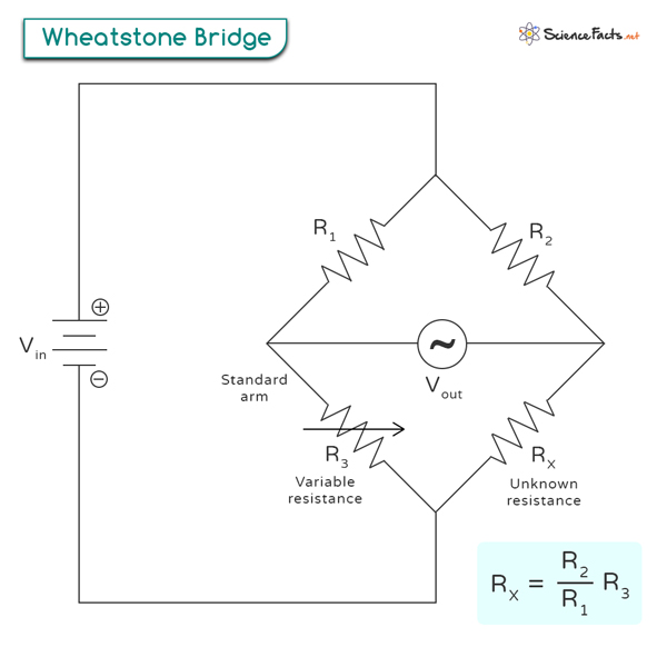
The Wheatstone bridge circuit consists of four resistive elements (R1, R2, R3, and RX) arranged in a diamond shape, forming two parallel branches, as shown in the image below. These branches are connected to a voltage source (Vin), typically a battery, and a galvanometer (VG), which detects current in the circuit.
The fundamental principle behind the operation of a Wheatstone bridge is the concept of balance and null deflection. When the resistances in the two branches are perfectly balanced, meaning they have equal ratios or values, no current flows through the galvanometer. It is known as a balanced bridge circuit.
Variable resistance is introduced into one of the branches, known as the standard arm of the Wheatstone bridge. By adjusting the known resistances R1 and R2 and the variable resistance R3 until the galvanometer reads zero current flow, it is possible to determine the value of the unknown resistance RX.
The balanced bridge circuit allows for highly accurate measurements because it eliminates any effects caused by variations in the voltage source or fluctuations in temperature. It is advantageous in applications requiring precise resistance measurements, such as laboratory experiments or industrial settings.
Formula
The formula for the Wheatstone bridge can be derived by considering the balance condition of the bridge. When the bridge is balanced, no current flows through the galvanometer, indicating that the ratio of resistances in one leg is equal to that in the other.
Mathematically, this can be expressed as:
R1/R2 = R3/Rx
Where
R1 and R2 are known resistors
R3 is a variable resistor used for balancing
Rx is the unknown resistor whose resistance we want to measure
By rearranging the equation, we can solve for Rx:
Rx = (R2/R1) * R3
This equation allows us to calculate the resistance of the unknown resistor based on the known resistances and the balance condition of the Wheatstone bridge.
The Wheatstone bridge equation can also be used to measure resistance changes. By monitoring changes in voltage across Rx or changes in current flowing through it, we can determine any variations in its resistance.
Applications
The Wheatstone bridge is a versatile circuit with numerous applications, particularly engineering. Here are some typical applications:
- Engineering: The Wheatstone bridge is extensively used in engineering to measure electrical resistance and detect small changes in resistance. It is commonly employed in circuits for precise measurements, calibration, and testing of electrical components.
- Strain Gauge Measurement: Strain gauges are widely used to measure strain and deformation in various materials. By incorporating strain gauges into a Wheatstone bridge circuit, engineers can accurately measure the strain experienced by an object under load. This application is commonly used in structural engineering, the aerospace industry, and material testing.
- Pressure Sensing: The Wheatstone bridge is utilized in pressure sensors to measure changes in pressure. By integrating a pressure-sensitive element into the bridge circuit, any variation in pressure causes a change in resistance, resulting in an output voltage that can be measured and calibrated to determine the pressure accurately. This application is commonly found in automotive, industrial, and medical devices.
- Temperature Sensing: Temperature sensors based on resistance variation, such as thermistors and RTDs (Resistance Temperature Detectors), can be connected to a Wheatstone bridge to measure temperature changes accurately. The output voltage of the bridge varies with temperature, allowing for precise temperature sensing and control in applications like HVAC systems, industrial processes, and scientific research.
Wheatstone Bridge Strain Gauge
Strain gauges play a crucial role in Wheatstone bridge measurements. Strain gauges are one of the resistive elements in the Wheatstone bridge configuration.
The working principle of a strain gauge is based on the fact that when subjected to mechanical strain or deformation, the electrical resistance of specific materials changes. Strain gauges are typically made of a thin metal foil or wire bonded to a surface or embedded in a material. When the material experiences strain, the strain gauge deforms, causing a change in its resistance.
In a Wheatstone bridge configuration, strain gauges are connected in a balanced bridge circuit. The circuit has four resistive elements – two strain gauges and two precision resistors. When no strain is applied, the bridge circuit is balanced, with no output voltage.
However, their resistance changes when strain is applied to one or both strain gauges. This imbalance in resistance causes an output voltage to be generated across the bridge. The magnitude and polarity of this voltage depend on the amount and direction of the applied strain. By measuring this output voltage and knowing the characteristics of the strain gauge, such as gauge factor and sensitivity, it is possible to determine the applied strain or deformation accurately.
Strain gauges are widely used in various applications, including structural monitoring, load cells, pressure sensors, and torque measurement devices. Their high sensitivity and ability to measure small changes in resistance make them invaluable for precise measurements in engineering and scientific fields.
-
References
Article was last reviewed on Thursday, August 31, 2023
Related articles


Join our Newsletter
Fill your E-mail Address