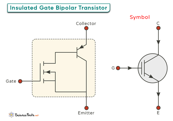
Insulated Gate Bipolar Transistor
The Insulated Gate Bipolar Transistor (IGBT) is a hybrid device that combines the best characteristics of a traditional Bipolar Junction Transistor (BJT) and a Metal-Oxide-Semiconductor Field-Effect Transistor (MOSFET). Specifically, it merges the high input impedance of a MOSFET with the excellent current handling capability of a BJT. It is a crucial component in modern electronics, known for its ability to handle high currents and voltages efficiently while offering fast switching speeds.
Structure and Composition
Basic Structure
The IGBT consists of three layers of semiconductor materials: an N-doped drift region in the middle and a P-doped emitter and collector regions on either side. The emitter and collector regions are heavily doped, meaning they have a lot of charge carriers (electrons and holes). This setup is similar to a traditional BJT. This heavy doping allows the IGBT to handle high currents.
Unique Gate Structure
What makes the IGBT different from other transistors is the addition of a gate structure, like in a MOSFET, on top of the drift region. This gate is separated from the drift region by a thin insulating layer, usually silicon dioxide (SiO2), allowing precise control over the device. The gate structure has a metal electrode separated from the drift region by the insulating layer.
Operation
Starting the Operation
The operation of an IGBT begins when a voltage is applied to the gate terminal. When a positive voltage is applied to the gate compared to the emitter, it creates an electric field. This field attracts electrons towards the gate, allowing electricity to flow between the collector and emitter regions.
Entering the On State
When the gate voltage reaches a certain level, called the threshold, the IGBT turns on. In this “on-state”, current can flow easily from the collector to the emitter. The voltage applied to the gate controls how well the channel conducts electricity, allowing precise control over the current flow.
Advantages
- BJT’s output stage allows it to handle large currents with minimal voltage drop
- MOSFET’s input stage provides fast switching speeds and high input impedance
This combination gives IGBTs the ability to handle high voltage and current simultaneously. They are well-suited for a wide range of applications.
Applications
- Motor Control: It can control the speed of electric motors in variable frequency drives (VFDs). By modulating the voltage and frequency supplied to the motor, IGBT-based VFDs enable energy-efficient operation and precise control over motor speed, torque, and direction. This makes them indispensable in industries ranging from manufacturing and transportation to HVAC systems and robotics.
- Renewable Energy: In solar and wind power inverters, IGBT converts DC power generated by solar panels or wind turbines into AC power suitable for homes, businesses, and the grid. Their high efficiency and robust switching capabilities make IGBTs essential for maximizing the energy yield and reliability of renewable energy installations, thereby contributing to the global transition towards sustainable energy sources.
- High-voltage Direct Current (HVDC) Transmission: It can convert, control, and transmit large amounts of electrical power over long distances. HVDC systems using IGBT-based converters offer lower transmission losses, improved voltage control, and enhanced grid stability compared to traditional alternating current (AC) transmission systems, making them ideal for interconnecting power grids, integrating renewable energy sources, and supplying power to remote areas.
-
References
Article was last reviewed on Tuesday, June 10, 2025
Related articles


Join our Newsletter
Fill your E-mail Address